EPC/PPC-CM5-070
Version 1.0
Product Overview
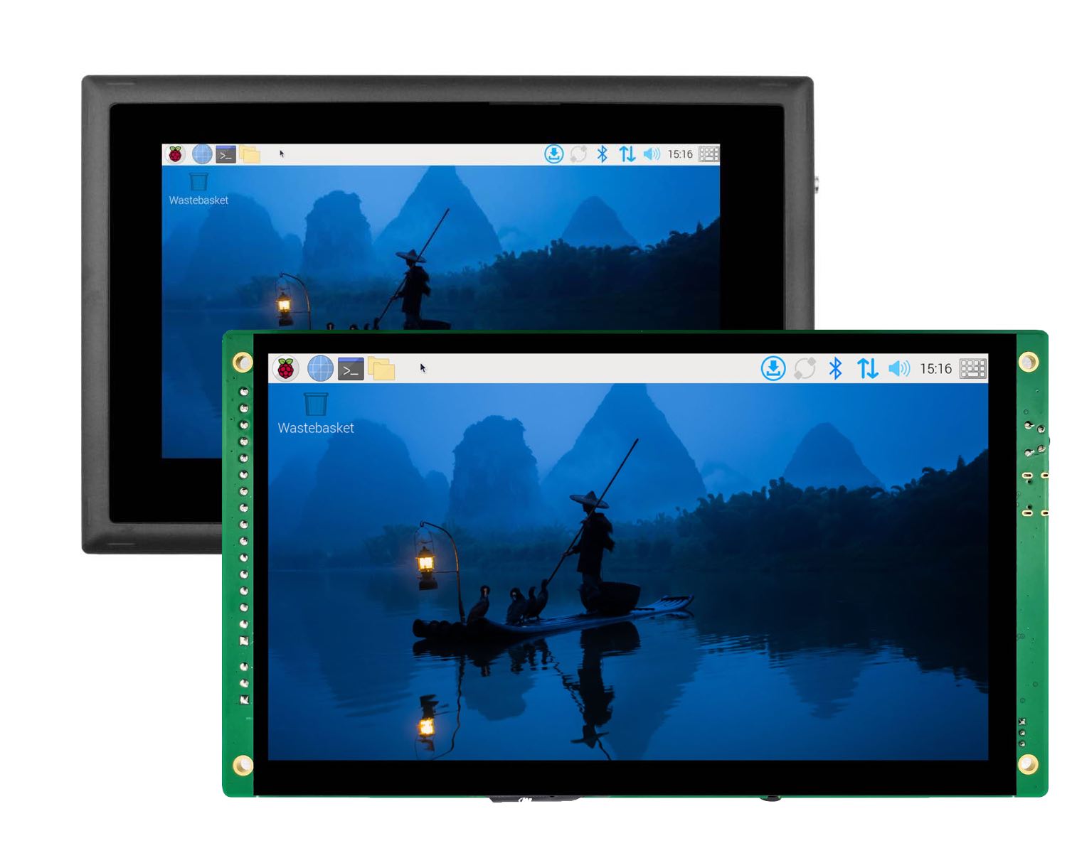
The Cortex®-A76 Raspberry Pi® series EPC/PPC-CM5-070 (PN: CS10600RA5070) is a high-quality industrial Pi PC. It features a 7” five-point capacitive touch screen with a resolution of 1024 x 600 pixels and brightness of 500 cd/m2.
It is available as a device hosed in a casing with bezels, thus facilitating different installation options:
Installation on an industrial cabinet
Integration with the existing equipment
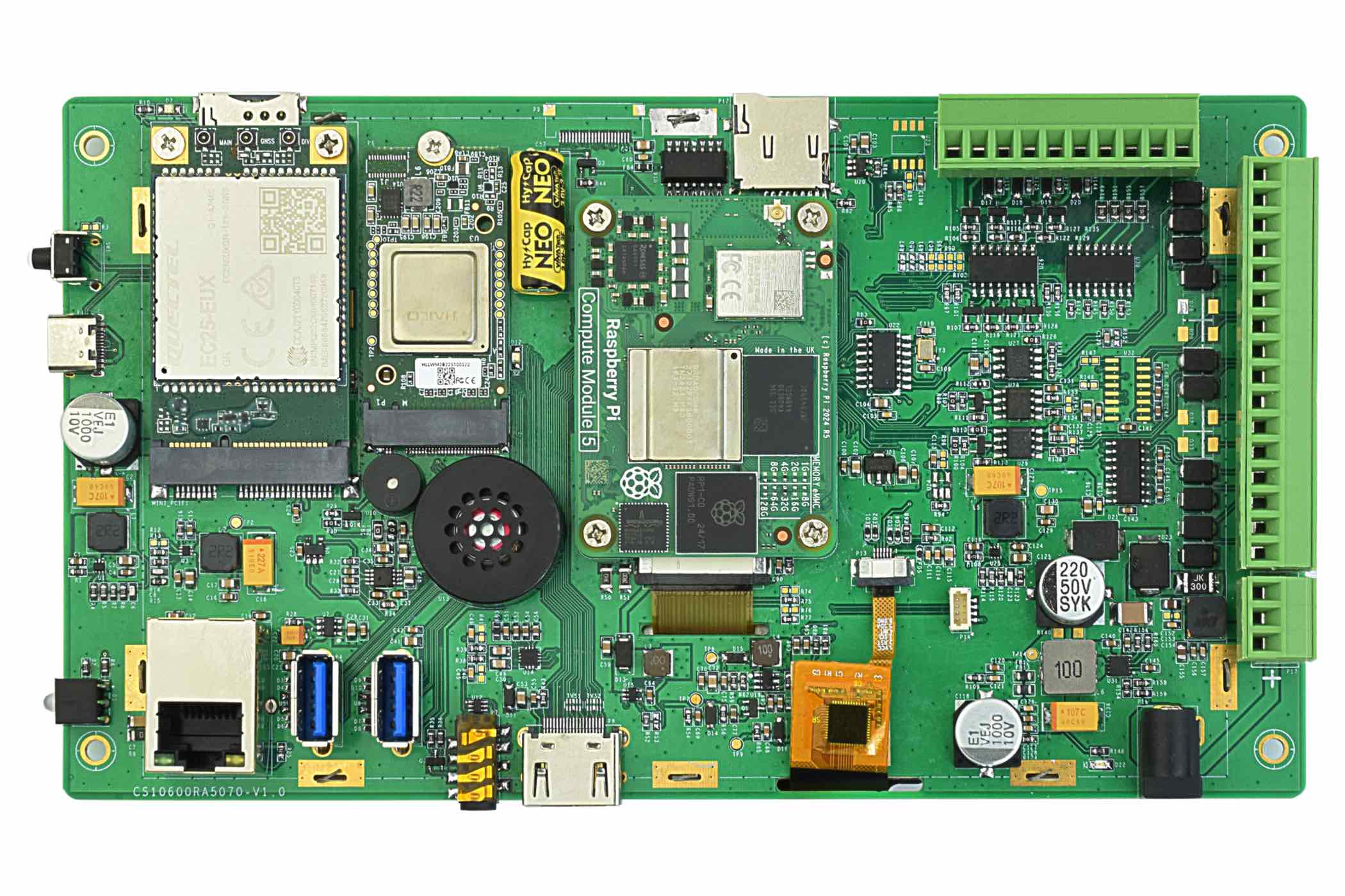
The EPC/PPC-CM5-070 industrial Pi PC is based around the powerful Raspberry Pi® Compute Module 5, powered by the Quad Cortex®-A76 processor with a processor speed of 2.4GHz.
Ordering Options
Chipsee products can be customized during the ordering process. The product will be shipped with the pre-installed factory defaults if no extra requirements are specified. The table in the Specifications section provides information about the default options bundled with the product.
Note
You can order PPC-CM5-070 from the official Chipsee Store or from your nearest distributor.
Pi® CM5 Module
The Pi® Compute Module 5 appears in different versions (different RAM size: 2GB, 4GB, or 8GB SDRAM based on CM5 and different eMMC size: 0GB, 16GB, 32GB, or 64GB based on CM5).
The EPC/PPC-CM5-070 industrial Pi PC does not include the CM5 Raspberry Pi® module by default.
If you would like to purchase it with a CM5, you can select it at the Chipsee store during the ordering process.
Operating System
This product comes with a pre-installed Raspberry Pi OS. Chipsee software engineers have created all the drivers, so every hardware feature is readily available for any standard development tool.
If your project requires a different OS, please Contact us, and we’ll make a customized version that suits your needs.
Optional Features
The EPC/PPC-CM5-070 industrial Pi PC does not include the 3G/4G/LTE modules by default. These modules are optional and can be selected at the Chipsee store during the ordering process.
The product has a PCIe Gen 2 × 1 (5Gbps), M.2 M-Key 2230/2242 socket (PCIe 3.0 is possible but experimental for CM5), you can use it with your NVMe SSD or other modules that can fit in the slot and supports the protocol. By default the NVMe SSD is not mounted.
Warning
Specifications
The EPC/PPC-CM5-070 industrial Pi PC offers a broad range of performance and connectivity options for scalable integration, providing expandability according to future needs. Some of the key features are listed in the table below.
EPC/PPC-CM5-070 |
|
|---|---|
CPU |
Raspberry Pi® CM5/CM5Lite; BCM2712 Quad(4) Core Cortex-A76 at 2.4GHz |
RAM |
2GB, 4GB, or 8GB SDRAM based on CM5 |
eMMC |
0GB, 16GB, 32GB, or 64GB based on CM5 |
Display |
7” IPS LCD, 1024 x 600 px, brightness 500 cd/m2 |
Touch |
5-point capacitive touch with 1mm Armored Glass |
Storage |
Support for 1 x TF Card3 |
PCIe |
PCIe Gen 2 × 1 (5Gbps), M.2 M-Key 2230/2242 socket |
USB |
2 x USB 3.0 type-A Host, 1 x USB type-C OTG |
LAN |
1 x Giga LAN |
Audio |
3.5mm Audio Out Connector, 2W Speaker Internal |
Buzzer |
Onboard Buzzer, driven by GPIO |
RTC |
High accuracy RTC with farad capacitor, can work 1 week after power off |
RS232 |
Default to 2 x RS232, up to 4 x RS232 |
RS485 |
Default to 2 x RS4851, these 2 x RS485 can be configured as 2 x RS232 |
CAN |
1 x CAN FD BUS, Arbitration Bit Rate up to 1Mbps, Data Bit Rate up to 8Mbps |
GPIO |
8 Channels, 4 Input, 4 Output |
I2C |
Not Supported |
WiFi/BT |
Optional (Depends on CM5)2 |
ZIGBEE |
No |
HDMI |
1 x HDMI 2.0 out, can be driven up to 4K 60FPS |
3G/4G/LTE |
Supported, not mounted by default |
Camera |
Yes, not mounted by default. Available on the board in the embedded PC. |
Power Input |
9V to 36V |
Current |
950mA max at 12V, 500mA typical at 12V |
Power Consumption |
11.4W max, 6W typical |
Working Temperature |
From -10°C to +60°C |
OS |
Raspberry Pi OS |
Dimensions |
CS10600RA5070E: 190 × 107.8 × 27.7 mm; CS10600RA5070P: 206 x 135 x 30mm |
Weight |
CS10600RA5070E: 400g; CS10600RA5070P: 700g |
Mounting Method |
CS10600RA5070E: Embedded; CS10600RA5070P: Panel, VESA |
- 1
The RS485 circuit controls the Input and Output direction automatically, there’s no need to control it from within the software.
- 2
The default product without the CM5 does not include a Wi-Fi/BT module. You can include a CM5 that has the Wi-Fi/BT module at the Chipsee store during the ordering process.
- 3
TF card slot, only used with CM5 Lite to boot system, cannot be used as external storage for CM5
Power Input
The EPC/PPC-CM5-070 industrial Pi PC can be powered by a wide range of input voltages: 9V to 36V DC. There are two types of power input connectors. One is a 3 Pin, 3.81mm screw terminal connector, and the other is a 2.1mm DC input head. As shown in the figure below.
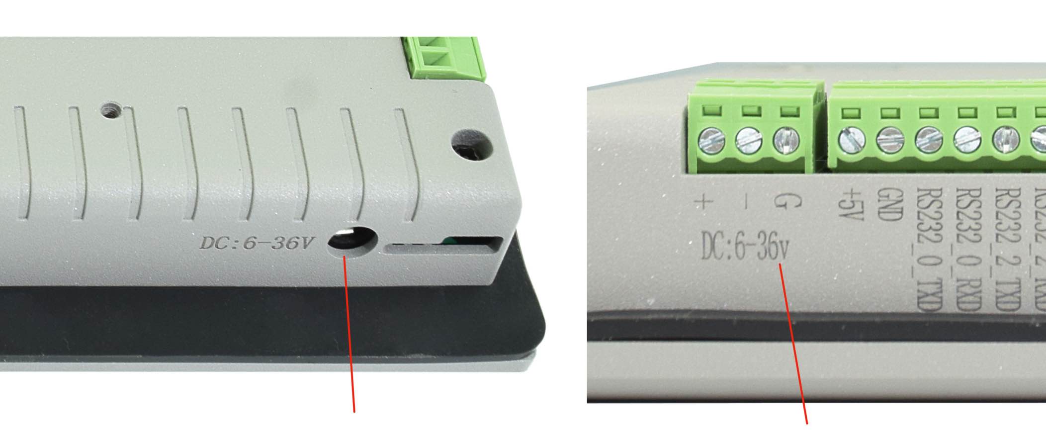
Power Input
Note that the “+” sign represents the positive power input, and it is printed both at the casing and as a silk-screen on the board of the embedded version. The “-” terminal is shorted to the ground.
Power Input Definition |
||
|---|---|---|
Pin Number |
Definition |
Description |
Pin 1 |
Positive Input |
DC Power Positive Terminal |
Pin 2 |
Negative Input |
DC Power Negative Terminal |
Pin 3 |
Ground |
Power System Ground |
Note
The system ground “G” is connected to power negative “-” on board.
The other power input port is a 2.1mm x 5.5mm x 9.5mm DC jack. For a proper DC power connector, refer to the figure below.
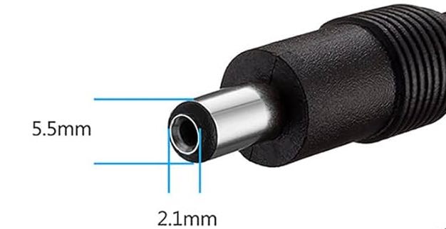
DC Jack
Touch Screen
The EPC/PPC-CM5-070 industrial Pi PC uses a 5-point capacitive touch with 1mm Armored Glass screen. However, the Raspberry Pi OS supports only One-Point touch.
The figure below shows the capacitive touch screen connected to the motherboard via the FPC connector.
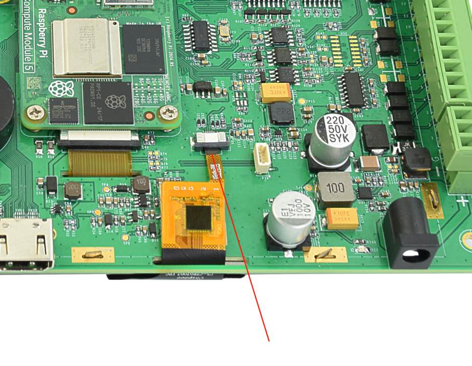
Capacitive Touch Connector
Attention
A capacitive touch screen is susceptible to power noise and Electromagnetic Radiation (EMR). It may cause LCD ripples or even capacitive touch malfunction. If using a capacitive multi-touch test application, you might notice the touch points float erratically across the display. There are several solutions to this problem:
Use a high-quality Power Adapter Unit (PSU) with low EMR. You can also provide power from a battery.
Make sure that the EPC/PPC-CM5-070 Power Input connector (pin 3) is properly connected to the Power System Ground to provide sufficient EMI shielding and eliminate the problem entirely.
Bad GND problems can also be confirmed by touching pin 3 of the Power Input connector with one hand while operating the capacitive touch screen with the other hand. In this case, the operator’s body acts as the Power System Ground.
Connectivity
There are many connectivity options available on the EPC/PPC-CM5-070 industrial Pi PC. It has 2 x USB 3.0 type-A Host, 1 x USB type-C OTG, 1 x Giga LAN (RJ45) Ethernet connector supporting up to 1 Gbps, and 4 x UART and 1 x CAN terminals (RS232/RS485/CAN).
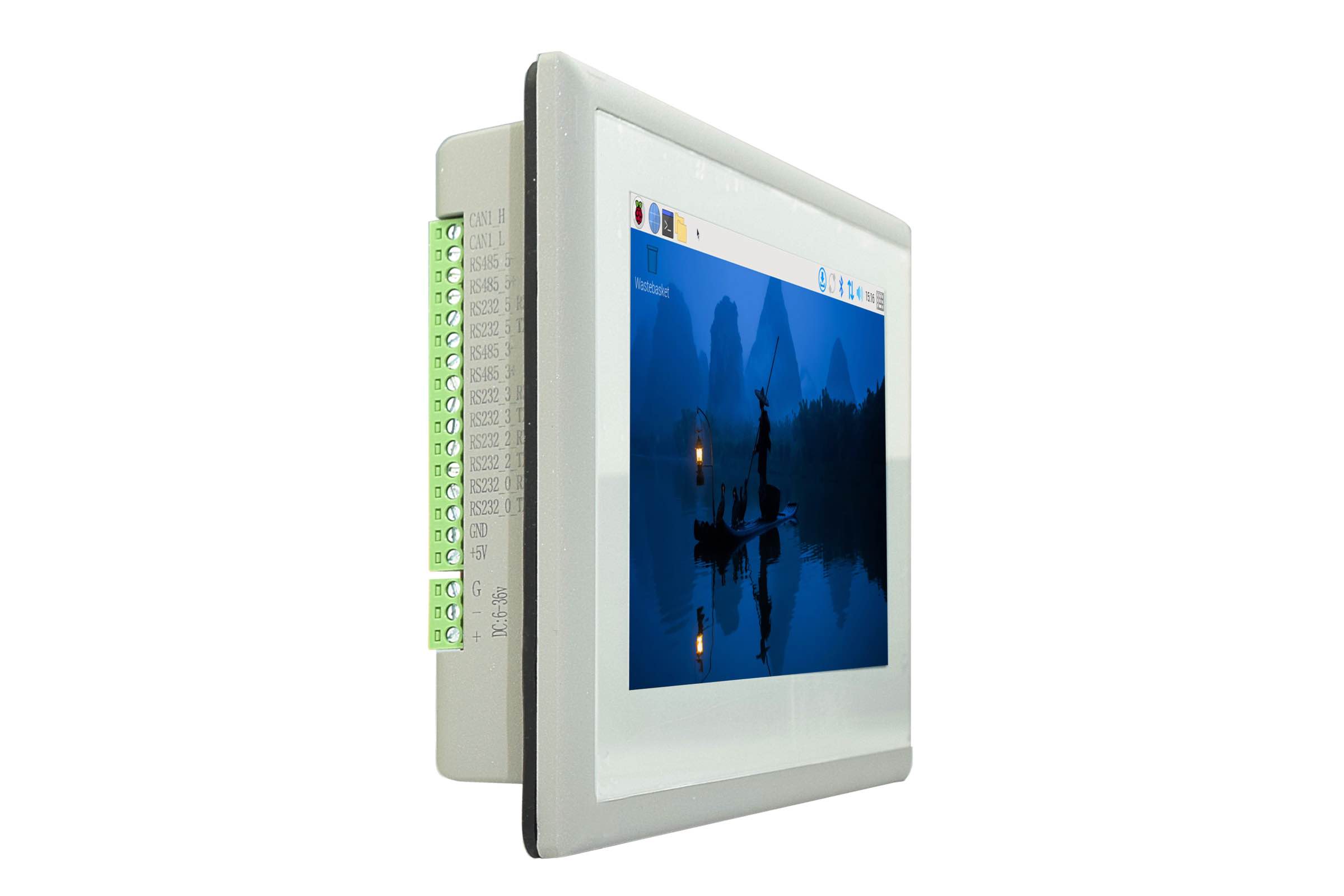
RS232/RS485/CAN
The serial communication interfaces (RS485, RS232, and CAN) are routed to a 16-pin 3.81mm terminal, as illustrated in the figure below.
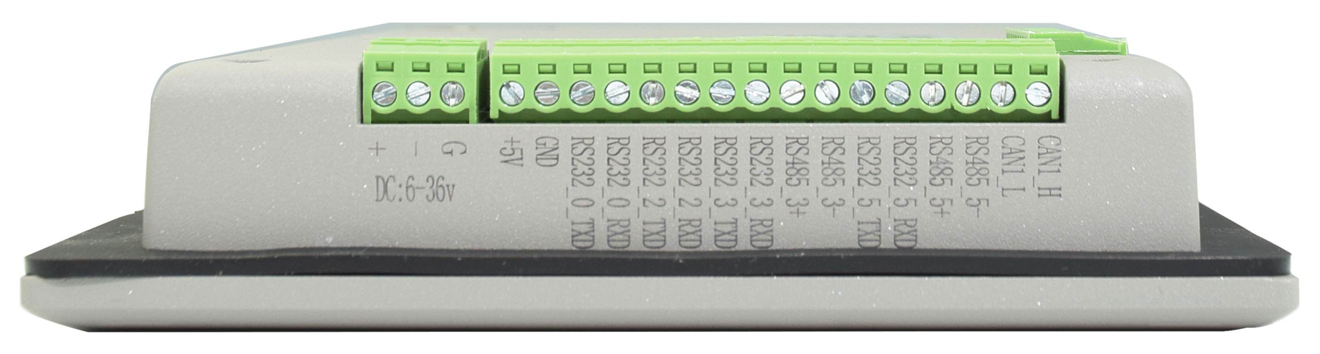
RS232-RS485-CAN on the EPC/PPC-CM5-070 Industrial PC
RS232 / RS485 / CAN Pin Definition: |
|||
|---|---|---|---|
Pin Number |
Definition |
Description |
OS Node |
Pin 16 |
CAN_H |
CPU SPI0, CAN BUS “H” signal |
CAN0 |
Pin 15 |
CAN_L |
CPU SPI0, CAN BUS “L” signal |
|
Pin 14 |
RS485_5- |
CPU UART5, RS485 –(B) signal |
/dev/ttyAMA4 |
Pin 13 |
RS485_5+ |
CPU UART5, RS485 +(A) signal |
|
Pin 12 |
RS232_5_RXD |
CPU UART5, RS232 RXD signal |
/dev/ttyAMA4 |
Pin 11 |
RS232_5_TXD |
CPU UART5, RS232 TXD signal |
|
Pin 10 |
RS485_3- |
CPU UART3, RS485 –(B) signal |
/dev/ttyAMA2 |
Pin 9 |
RS485_3+ |
CPU UART3, RS485 +(A) signal |
|
Pin 8 |
RS232_3_RXD |
CPU UART3, RS232 RXD signal |
/dev/ttyAMA2 |
Pin 7 |
RS232_3_TXD |
CPU UART3, RS232 TXD signal |
|
Pin 6 |
RS232_2_RXD |
CPU UART2, RS232 RXD signal |
/dev/ttyAMA1 |
Pin 5 |
RS232_2_TXD |
CPU UART2, RS232 TXD signal |
|
Pin 4 |
RS232_0_RXD |
CPU UART0, RS232 RXD signal, Debug Port |
/dev/ttyAMA0 |
Pin 3 |
RS232_0_TXD |
CPU UART0, RS232 TXD signal, Debug Port |
|
Pin 2 |
GND |
System Ground |
|
Pin 1 |
+5V |
System +5V Power Output, No more than 1A Current output |
|
Attention
RS485_3 and RS485_5 can control the input and output direction automatically. There’s no need to control it from within the software.
The 120Ω match resistor for RS485 is NOT mounted by default.
The 120Ω match resistor for CAN is NOT mounted by default. Be sure to mount the match resistor when testing CAN.
RS485_3 and RS232_3 share UART3 and can’t work at the same time; RS485_5 and RS232_5 share UART5 and can’t work at the same time. Meaning the product provides 4 x RS232 + 0 x RS485, or 2 x RS232 + 2 x RS485, or 3 x RS232 + 1 x RS485.
GPIO Port
The EPC/PPC-CM5-070 industrial Pi PC has a 10 Pin 3.81mm GPIO Connector, as shown in the figure below. The table below gives details about the definition of every Pin.
Attention
In order to use the Isolated Output, you need to add an external Isolated Power to the VDD_ISO and GND_ISO. The power voltage should not exceed 24V.
The output current can achieve 500mA for every channel, but it also depends on the isolated power that is connected.
In order to use the Isolated Input, you need to add a signal to the ISO_InputX and GND_ISO. A 2.4KΩ resistor, as R6, has been added to limit the input current, as shown in the figure below. This resistor should work well for the 5-24V input signal. If your input signal is less than 5V, please change this input resistor. The reduced schematic is for reference purpose, if you need the precise resistor schematic, please contact us.
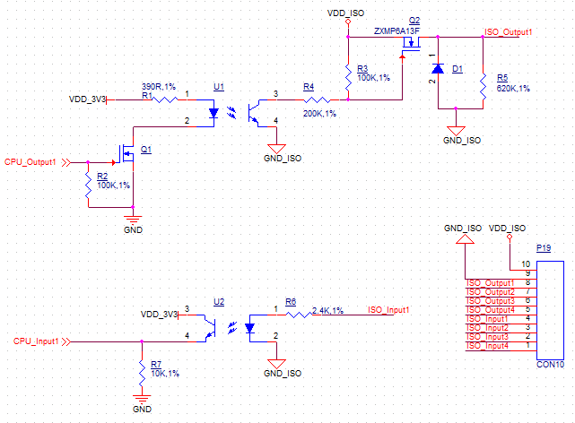
Isolated GPIO reduced schematic
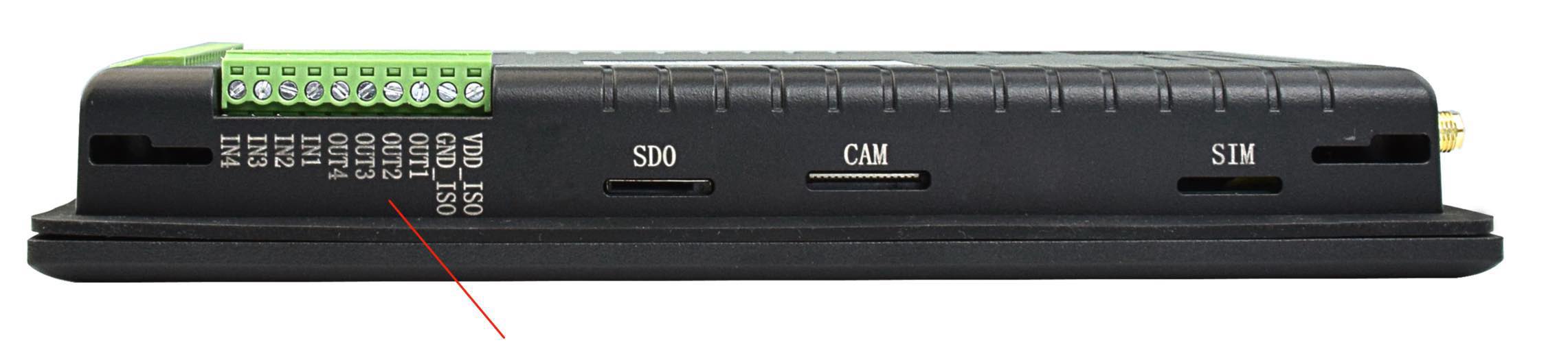
GPIO Connector
GPIO Connector Pin Definition: |
||
|---|---|---|
Pin Number |
Definition |
Description |
Pin 10 |
VDD_ISO |
Isolated Power +5V ~ +24V Input |
Pin 9 |
GND_ISO |
Isolated Ground |
Pin 8 |
OUT1 |
Isolated Output 1 |
Pin 7 |
OUT2 |
Isolated Output 2 |
Pin 6 |
OUT3 |
Isolated Output 3 |
Pin 5 |
OUT4 |
Isolated Output 4 |
Pin 4 |
IN1 |
Isolated Input 1 |
Pin 3 |
IN2 |
Isolated Input 2 |
Pin 2 |
IN3 |
Isolated Input 3 |
Pin 1 |
IN4 |
Isolated Input 4 |
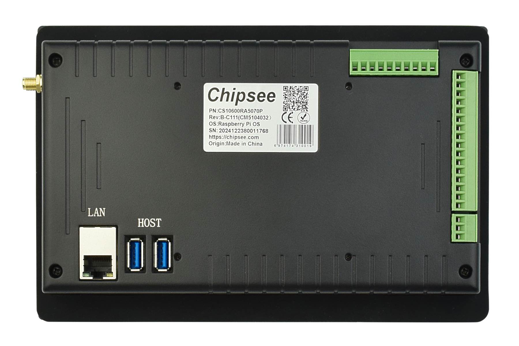
USB Connectors
There are 2 x USB 3.0 type-A Host, 1 x USB type-C OTG onboard, as shown in the figure below.
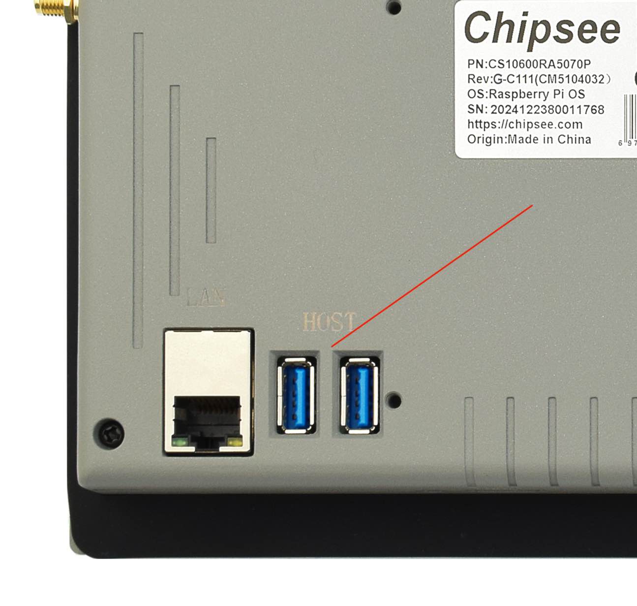
USB HOST Connectors
Attention
1. These two USB host connectors can drive 500mA for each channel at most.
2. These two USB host connectors come from the same USB HUB.
3. When you connect this product to the HOST PC through the Type-C port, the USB HUB will be disabled. As a result, the two USB host connectors will not work.
The product has one USB Type-C OTG connector that works as a slave by default. You can use it to establish a connection with the host PC and for downloading the system to the eMMC of CM5 module.
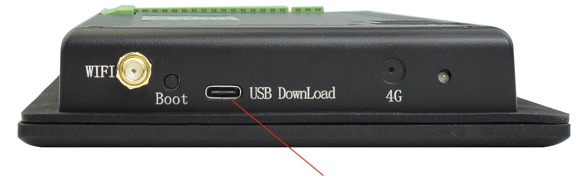
USB Type-C OTG Connector
Warning
Be careful not to touch surrounding electronic components accidentally while plugging in USB devices into the embedded Industrial PC version.
Remember to unplug the Type-C cable after flashing OS, otherwise the USB hosts won’t work.
LAN
The 1 x Giga LAN provides Ethernet connectivity over standardized Ethernet cables as shown in the figure below. The integrated Ethernet interface supports up to 1 Gbps data throughput. These Giga LAN signals come from the CM5 module directly.
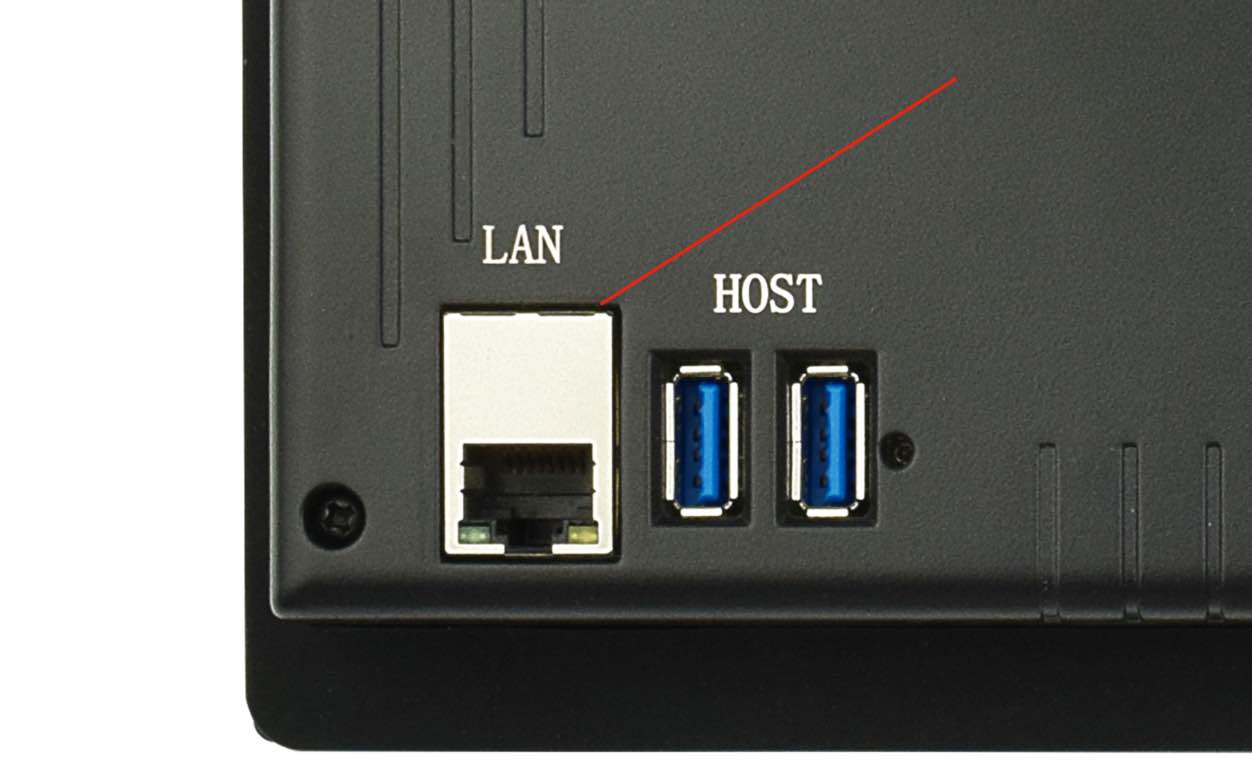
RJ45 LAN Connector
Note
Use CAT5 or better cables to achieve full data throughput over maximum distance defined by the 1000BASE-T standard (100m).
WiFi & BT Module
The default EPC/PPC-CM5-070 without the CM5 does not include a Wi-Fi/BT module.
If you include a CM5 that has the Wi-Fi/BT module, the product will have Wi-Fi/BT feature.
The product also has an SMA connector for an external WiFi/BT antenna:
WiFi+BT Antenna
Attention
The product does not come shipped with the Wi-Fi/BT module by default.
3G/4G/LTE Module
The EPC/PPC-CM5-070 industrial Pi PC is equipped with a mini-PCIe connector that can connect to a 3G/4G/LTE module. The customer will also need a SIM Card Holder and a 3G/4G/LTE antenna to ensure 3G/4G/LTE works on the EPC/PPC-CM5-070. SIM card does NOT support hot plug. Power off before inserting or removing SIM card.
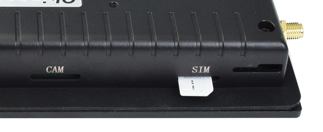
SIM Card Direction
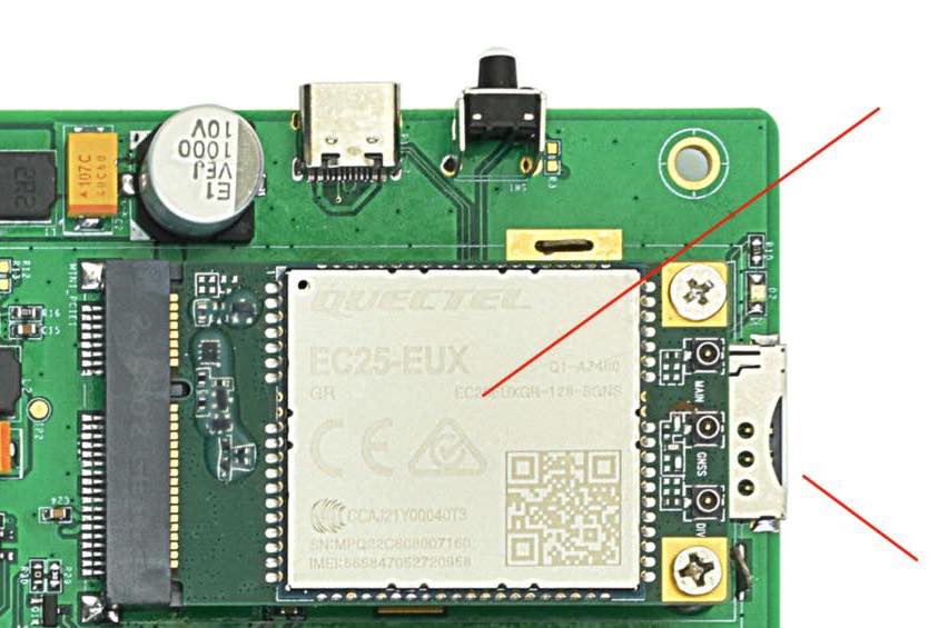
3G/4G/LTE Module and SIM Card Holder
Attention
The product does not come shipped with the 3G/4G/LTE module by default. If you need to use 3G/4G/LTE, you can contact us when placing an order, we can install the necessary hardware for you.
M.2 Module
The EPC/PPC-CM5-070 industrial Pi PC has a M.2 slot, it supports NVME m.2 SSD or other m.2 modules such as an AI compute module. It’s PCIe Gen 2 × 1 (5Gbps), M.2 M-Key 2230/2242 socket. The modules are not included in the product by default.
M.2 Connector
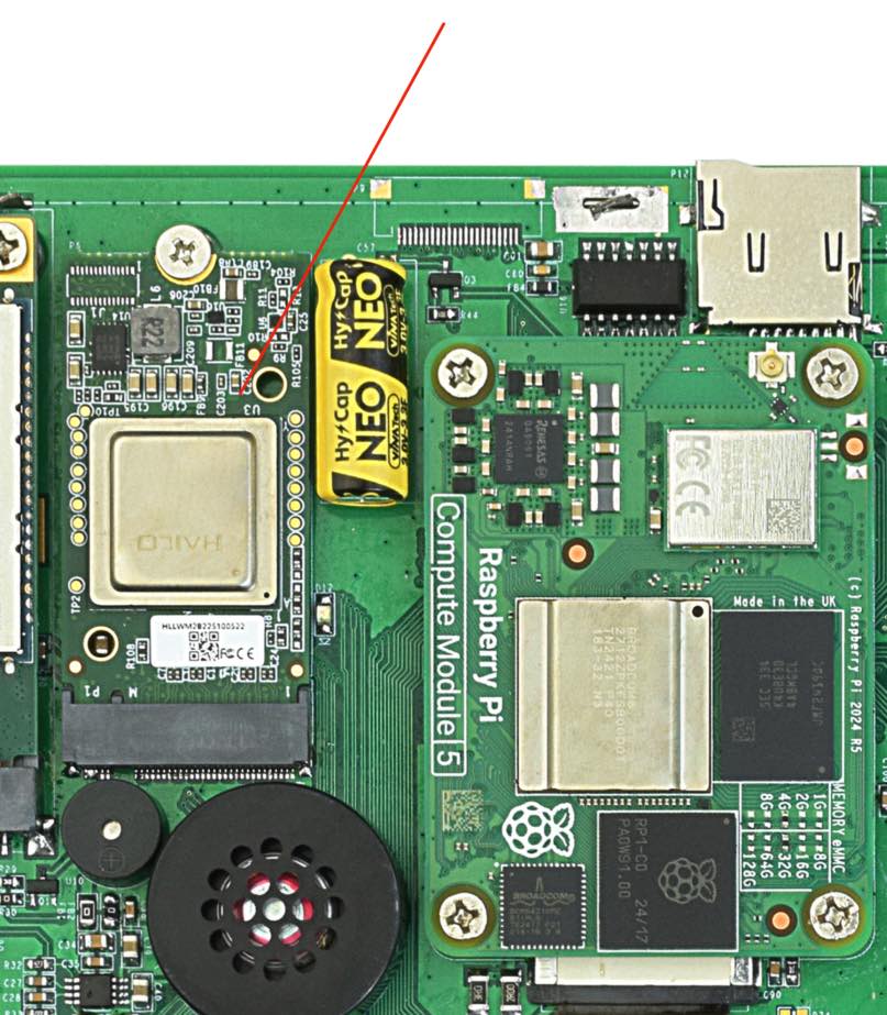
Camera Connector
The EPC/PPC-CM5-070 industrial Pi PC has a 22 Pin Camera Connector, as shown in the figure below. The camera signals come from CAM1. The table below gives details about the definition of every pin.
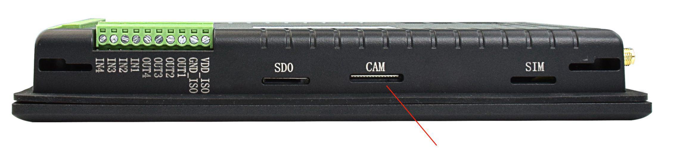
Camera Connector
Camera Connector Pin Definition: |
||
|---|---|---|
Pin Number |
Definition |
Description |
Pin 1 |
GND |
Power Ground |
Pin 2 |
CAM1_DN0 |
CSI Negative Channel 0 |
Pin 3 |
CAM1_DP0 |
CSI Positive Channel 0 |
Pin 4 |
GND |
Power Ground |
Pin 5 |
CAM1_DN1 |
CSI Negative Channel 1 |
Pin 6 |
CAM1_DP1 |
CSI Positive Channel 1 |
Pin 7 |
GND |
Power Ground |
Pin 8 |
CAM1_CN |
CSI Negative CLK |
Pin 9 |
CAM1_CP |
CSI Positive CLK |
Pin 10 |
GND |
Power Ground |
Pin 11 |
CAM1_DN2 |
CSI Negative Channel 2 |
Pin 12 |
CAM1_DP2 |
CSI Positive Channel 2 |
Pin 13 |
GND |
Power Ground |
Pin 14 |
CAM1_DN3 |
CSI Negative Channel 3 |
Pin 15 |
CAM1_DP3 |
CSI Positive Channel 3 |
Pin 16 |
GND |
Power Ground |
Pin 17 |
CAM_GPIO0 |
CAM GPIO0, use for disable camera power and module |
Pin 18 |
CAM_GPIO1 |
CAM GPIO1, use for disable camera power and module |
Pin 19 |
GND |
Power Ground |
Pin 20 |
SCL0 |
CPU I2C SCL0 signal |
Pin 21 |
SDA0 |
CPU I2C SDA0 signal |
Pin 22 |
+3.3V |
System +3.3V Power Output, No more than 500mA Current output |
Attention
The camera connector is supported but not mounted by default. Please contact us when placing an order if you need to use camera on the EPC/PPC-CM5-070.
TF Card Slot
The EPC/PPC-CM5-070 industrial Pi PC features 1 x TF Card (micro SD) slot. A slot can address up to 128GB of memory.
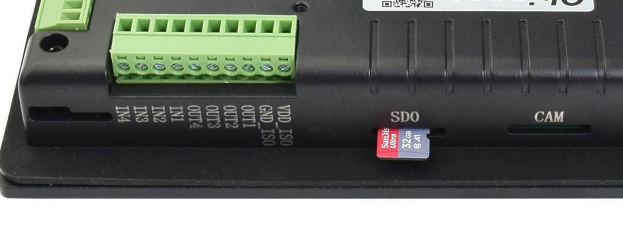
TF (micro SD) Card Slot
Attention
The TF card cannot be used for memory extension. It is only used for system boot-up for CM5 LITE model.
The product does not come shipped with the TF card by default.
Audio Connectors
The EPC/PPC-CM5-070 industrial Pi PC features some audio peripherals. It has 1 x 3.5mm audio output jack.
Also, the EPC/PPC-CM5-070 industrial Pi PC has a miniature 2W internal speaker for audio reproduction, as well as a small buzzer for alarm/notification sounds.
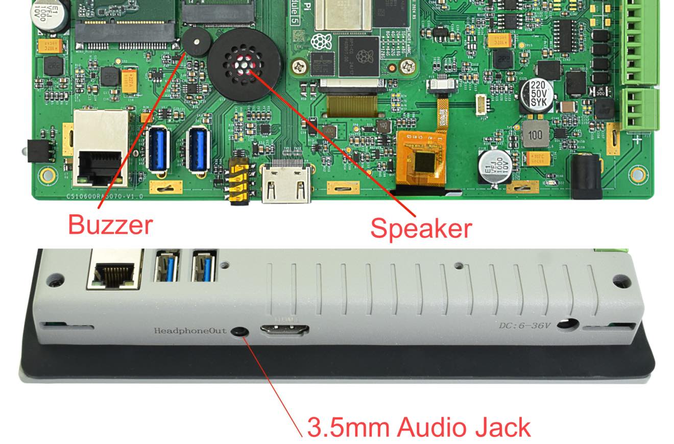
Audio Connector
Attention
By plugging in the headphone cable, the internal speaker will be disabled automatically.
HDMI Connector
The EPC/PPC-CM5-070 industrial Pi PC supports 1 x HDMI 2.0 out, can be driven up to 4K 60FPS.
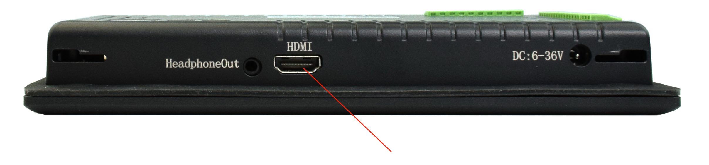
Micro HDMI Connector
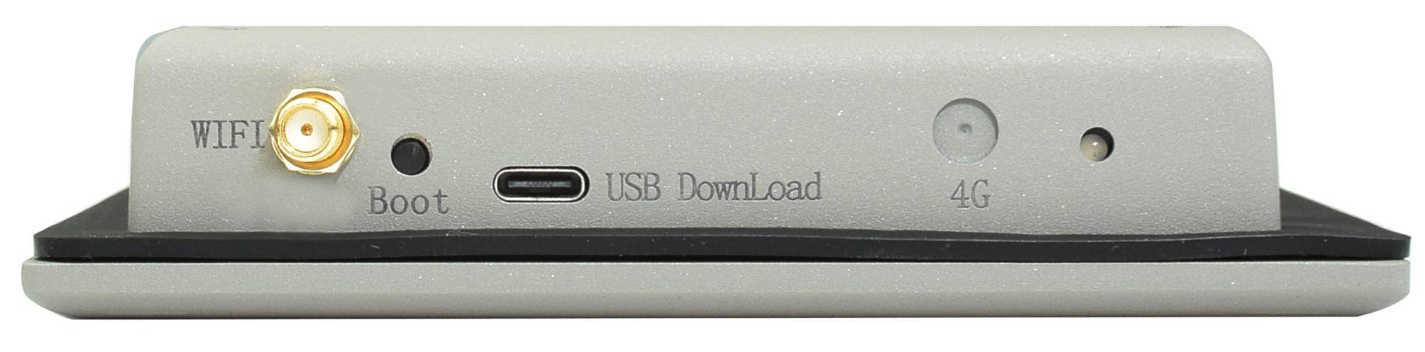
PROG Button
The EPC/PPC-CM5-070 industrial Pi PC has one button for entering usb download mode, as shown in the figure below.
When booting with the button being pressed, the Raspberry Pi will boot from the USB connector. You can use this feature to download the OS software to the internal eMMC.
When booting without pressing the button, the Raspberry Pi will boot from the internal eMMC.
There is no need to press the button during regular operation. However, if you need to reinstall the OS, please refer to the detailed information on how to reflash the OS from the Software Documentation.
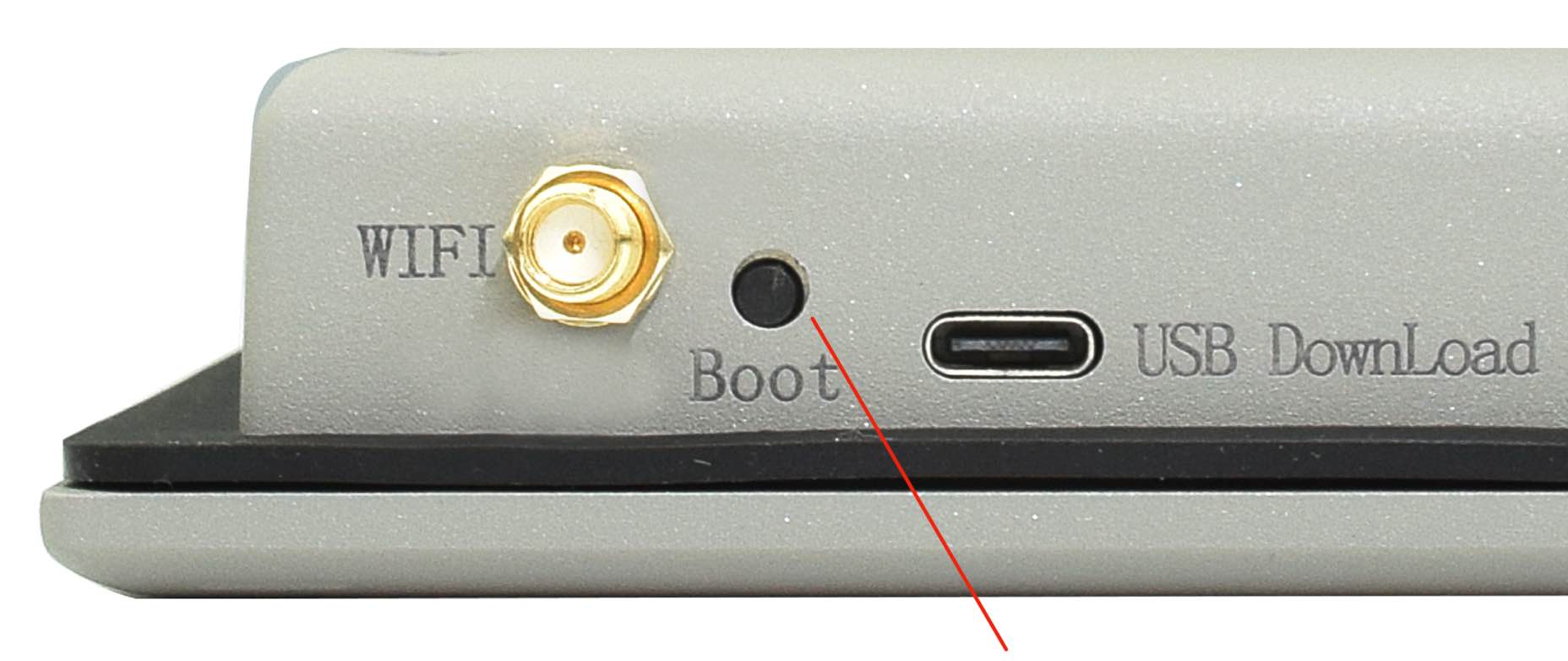
PROG Button
Mounting Procedure
The EPC/PPC-CM5-070 industrial Pi PC can be mounted with 4 x M4 screws, enabling simplified installation onto any standard mounting fixture.
CS10600RA5070P
You can mount CS10600RA5070P with VESA mounting (guide): 75 x 75 mm, 4 x M4 (6mm) screws.
You can mount CS10600RA5070P with PANEL mounting (guide).
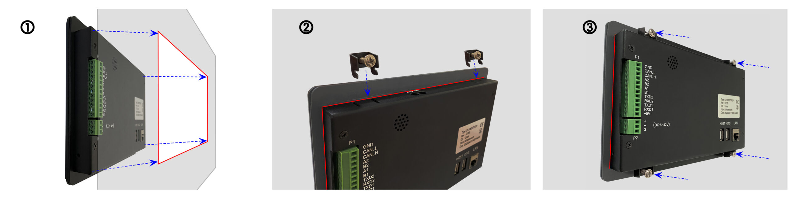
Figure 937: Panel mounting
CS10600RA5070E
You can mount CS10600RA5070E with the Embedded mounting (guide) method, as shown in the figure below.
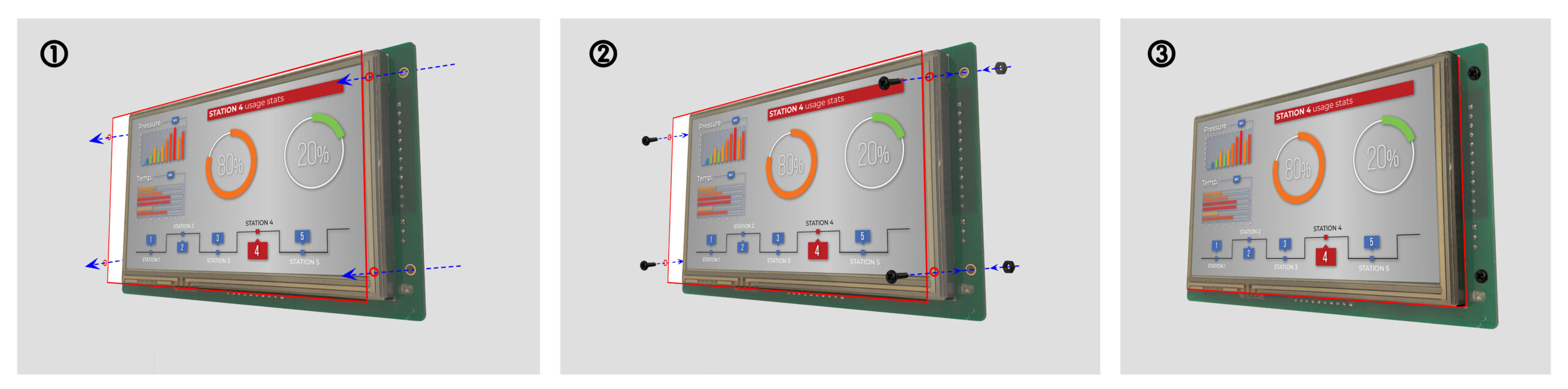
Figure 938: Embedded mounting
Attention
Please make sure the display is not exposed to high pressure when mounting into an enclosure.
You can find detailed information about mounting in the Mount IPC Guide.
Mechanical Specifications
CS10600RA5070P
For CS10600RA5070P, the outer mechanical dimensions are 206 x 135 x 30mm (W x L x H).
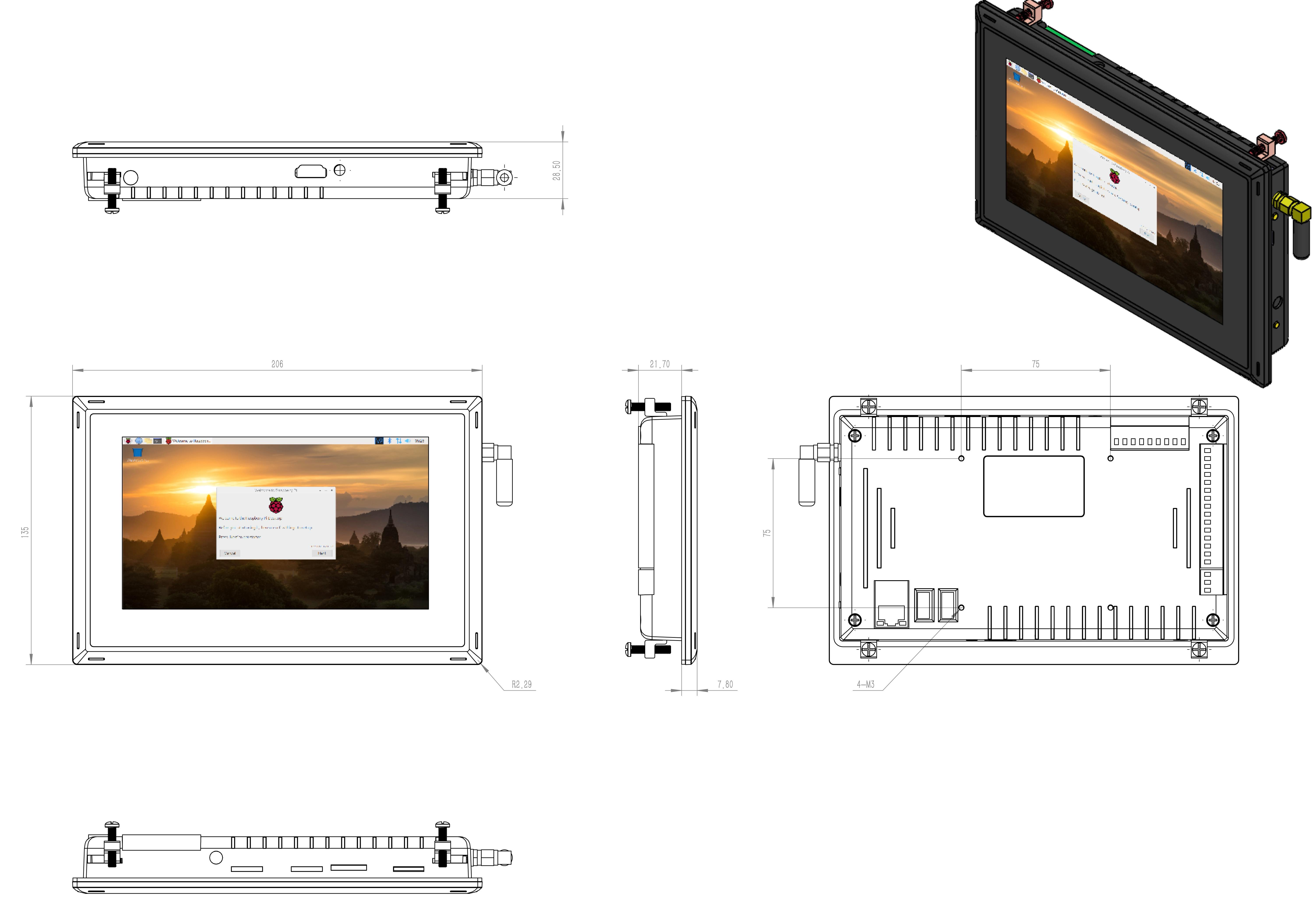
CS10600RA5070P Technical Drawing
CS10600RA5070E
For CS10600RA5070E, the outer mechanical dimensions are 190 × 107.8 × 27.7 mm (W x L x H).
Please refer to the technical drawing in the figure below for details related to the specific product measurements.
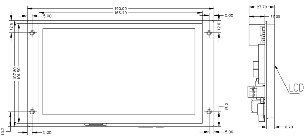
CS10600RA5070E Technical Drawing
Disclaimer
This document is provided strictly for informational purposes. Its contents are subject to change without notice. Chipsee assumes no responsibility for any errors that may occur in this document. Furthermore, Chipsee reserves the right to alter the hardware, software, and/or specifications set forth herein at any time without prior notice and undertakes no obligation to update the information contained in this document.
While every effort has been made to ensure the accuracy of the information contained herein, this document is not guaranteed to be error-free. Further, it does not offer any warranties or conditions, whether expressed orally or implied in law, including implied warranties and conditions of merchantability or fitness for a particular purpose. We specifically disclaim any liability with respect to this document, and no contractual obligations are formed either directly or indirectly by this document.
Despite our best efforts to maintain the accuracy of the information in this document, we assume no responsibility for errors or omissions, nor for damages resulting from the use of the information herein. Please note that Chipsee products are not authorized for use as critical components in life support devices or systems.
Technical Support
If you encounter any difficulties or have questions related to this document, we encourage you to refer to our other documentation for potential solutions. If you cannot find the solution you’re looking for, feel free to contact us. Please email Chipsee Technical Support at support@chipsee.com, providing all relevant information. We value your queries and suggestions and are committed to providing you with the assistance you require.