Ubuntu 12.04 OS
Ubuntu 12.04 OS User Manual
This manual provides users with a fast guide of Chipsee Industrial Computer (Abbreviate as IPC) about Ubuntu 12.04 OS development. Through this manual, users can quickly understand the hardware resources; users can build a complete compilation of Linux development environment; users can debug Ubuntu 12.04 OS via serial and Internet.
Revision |
Date |
Author |
Description |
|---|---|---|---|
V1.0 |
2021-12-30 |
Randy |
Revised |
SUPPORTED BOARDS:
CS10600F070 CS12800F101
PREBUILT FILES PACKAGE:
Prebuilt files for the various industrial PCs can be found in the OS Downloads.
Below are the links to the prebuilt files for each industrial PC model.
System Features
Feature |
Comment |
|---|---|
Kernel |
Kernel 3.14.52 |
Bootloader |
Uboot 2015.04 |
System |
Ubuntu 12.04 LTS |
Python |
Python 2.7.9 / Python 3.4.0 |
Qt |
Need to be installed by user |
GCC |
4.8.2 |
Desktop |
matchbox |
user/password |
[linaro/linaro] or [linaro/root] |
Preparation
You will need to prepare the following items before you can start using the Prebuilt Files Package to re-flash the system.
Power Supply Unit (PSU) with the appropriate voltages, as follows:
The CS12800F101 product needs a 12V to 36V power adapter.
The CS10600F070 product needs a 6V to 36V power adapter.
You need to prepare the Power Adapter by yourself
Hardware Requirements
Chipsee Industrial PC
PSU according to the instructions above
USB-to-serial or other serial cable for debugging
USB A-A cable (used only if the hardware configured as OTG)
Windows 7 PC
Mini-B USB OTG Cable
TF Card (at least 4GB) and card reader
Software Requirements
Ubuntu 12.04 OS Prebuilt Files Package (from the link above)
MFGTools
QT4.8.4 for Linux
Getting Started and Tests
Note
Throughout this section, the user can use both the pre-built Ubuntu 12.04 image files and the MFGTools software to burn files to the system, boot system and perform necessary software and hardware test.
Downloading images
Boot Switch Configuration
CS-IMX6 has a boot configuration select switch, as shown on the figure below. You can use the boot select switch to change between three modes, namely:
TF Card
eMMC Boot
Download

Figure 261: Boot Mode Setup
SW Mode |
1 |
2 |
3 |
4 |
|---|---|---|---|---|
TF Card |
1 |
0 |
0 |
0 |
eMMC |
1 |
1 |
0 |
1 |
Download |
0 |
1 |
1 |
0 |
Note
The user can use both the pre-built Ubuntu 12.04 image files and the MFGTools software to download new images to the system, boot system and perform necessary software and hardware test.
Prebuilt Files Package
You can get the Prebuilt Files Package for each model from links mentioned at the beginning of this documentation. You can also get the Prebuilt Files Package from the DVD in /Ubuntu 12.04/Prebuilds folder. However, it may be outdated so always compare the versions (the last number in the filename is the release date).
The prebuilt package has the following content:
Contents |
Comment |
|---|---|
boot/imx6q-eisd.dtb |
TF Card boot dtb file |
boot/u-boot-sd.imx |
TF Card boot bootloader |
boot/zImage |
TF Card boot kernel file |
boot/logo.bmp |
TF Card boot logo file |
filesystem/rootfs-emmc-flasher.tar.bz2 |
TF Card boot rootFS |
mksdcard.sh |
Shell tools to make bootable TF Card |
README |
Simple guidelines |
S1.jpg |
Boot Switch Config Figure |
emmc-flash/emmc/rootfs.tar.bz2 |
RootFS in target eMMC |
emmc-flash/emmc/u-boot-emmc.imx |
Bootloader in target eMMC |
emmc-flash/emmc/zImage |
Kernel file in target eMMC |
emmc-flash/emmc/zImage_framebuffer |
Kernel file with frame-buffer |
emmc-flash/emmc/imx6q-eisd.dtb |
Dtb file in target eMMC |
emmc-flash/emmc/imx6q-eisd.dtb_framebuffer |
Dtb file with frame-buffer |
emmc-flash/emmc/logo.bmp |
Logo file in eMMC |
emmc-flash/mkemmc.sh |
Shell tool to download images to eMMC |
Note
The default
zImageandimx6q-sabresd.dtbfiles support ‘keep the logo from uboot to kernel’ but don’t support framebuffer.We also provide
zImage_framebufferandimx6q-eisd.dtb_framebufferfile versions that support the framebuffer function but do not support the ‘keep the logo from uboot kernel’ feature. If you need the framebufer, just rename these two files tozImageandimx6q-eisd.dtb.
Downloading Images by using MFGTool
The MFGTools can be used to download images into a target device. It is a quick and easy tool for downloading images.
Before downloading images with the MFGTools, set the boot switch to download mode. (refer to Boot Switch Configuration above)
Configuring MFGTool
To configure MFGTool, follow these steps:
Untar
Mfgtools-K3035-Vx.x.zipfile.- Open the extracted folder
Mfgtools-K3035-Vx.xand editcfg.inifile. 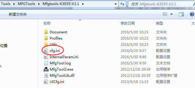
Figure 262: Extracted Folder
- Open the extracted folder
- In the
cfg.inifile, ensure thenamevariable is set toUbuntu-SabreSD-eMMC, as shown on the figure below. 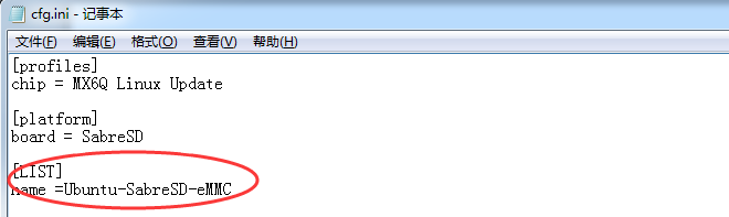
Figure 263: Cfg.ini file
Note
The default uImage disable the Frame buffer function. If you want to use Frame buffer, please rename the
uImage_has_consoletouImageto replace the defaultuImage.
- In the
Copy Image To Android Directory
Follow these steps to copy image to Linux directory:
Copy the images from prebuilt-xxx/emmc-flash/emmc/ to Mfgtools-K3035-Vx.x\Profiles\Linux\OS Firmware\files\ubuntu directory. Copy the logo file to Mfgtools-K3035-Vx.x\Profiles\MX6Q Linux Update\OS Firmware\files\logo directory and rename it to logo.bmp.
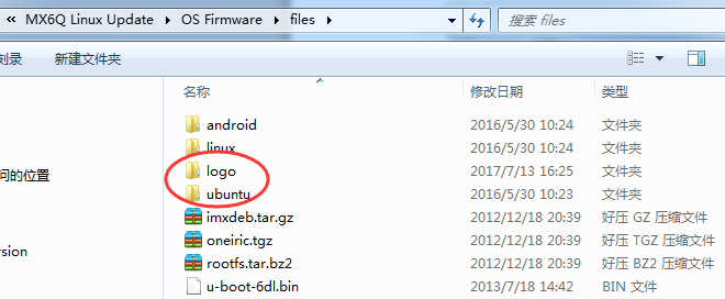
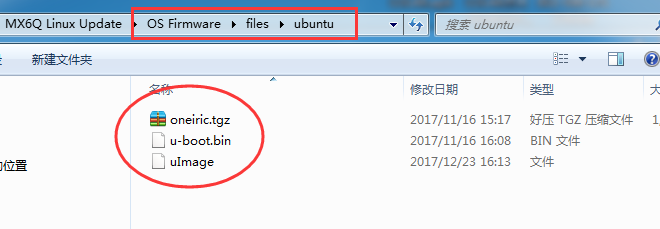
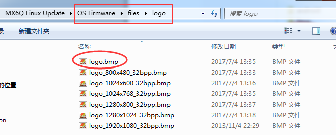
Figure 264: Prepare Images
Using MFGTool
Connect a USB OTG cable from a Windows PC to the USB OTG port on the IPC.
- Change the boot select configuration to 0 1 1 0, as shown on the figure below.
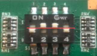
Figure 265: Boot Switch Config
Connect a 12V-2A power adapter to the IPC and power ON.
- On your Windows PC, open the
Mfgtools-Rel-XXX_XXXXXX_MX6Q_UPDATER_VXXdirectory and run theMfgTool2.exefile, as shown on the figure below. 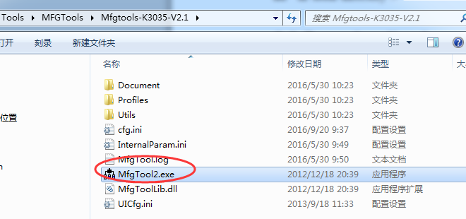
Figure 266: Run MfgTools2.exe file
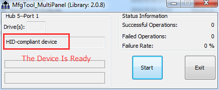
Figure 267: Prepare to start
Note
If you get a message saying No Device Connected, check the USB-OTG cable to ensure it is ready.
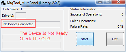
Figure 268: The USB-OTG cable is not connected correctly.
- On your Windows PC, open the
- When the process is complete, you click the Stop button to stop downloading Image and exit.
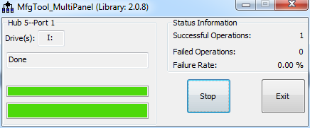
Figure 271: Download Image is finished
Downloading Images by using the TF card
Follow the steps below to download images onto the eMMC by using the TF Card:
Copy the Prebuilt Files Package to a Linux environment (such as Ubuntu 14.04).
Insert the SD card into your computer. If you are using virtual machines, please ensure the SD card is mounted to the Linux operating system.
- Confirm the SD card mount point,
/dev/sdX,(e.g.,/dev/sdcor/dev/sdb, be sure to use the right one). In a Linux system, you can use the command below to find out what X is. $ sudo fdisk –l
- Confirm the SD card mount point,
Copy the
prebuilt-imxv1-csXXXXXfXXXvX-android6-emmc-YYYYMMDD.tar.gzto somewhere(such as $HOME) on the Ubuntu PC.- Extract the
prebuilt-imxv1-csXXXXXfXXXvX-android6-emmc-YYYYMMDD.tar.gz $ tar -xzvf prebuilt-imxv1-csXXXXXfXXXvX-android6-emmc-YYYYMMDD.tar.gz
- Extract the
- Go to the folder
$ cd prebuilt-imxv1-csXXXXXfXXXvX-android6-emmc-YYYYMMDD
- Use the following command to flash the Ubuntu 12.04 OS to the SD card
$ sudo ./mksdcard.sh --device /dev/sd<?>
Note
sd<?> means the SD card mount point, (e.g.,
/dev/sdcor/dev/sdb) in Ubuntu system.The recommended SD card should be Sandisk Class4 level SD card or above.
The bootable SD Card is now ready. Power OFF the industrial PC and insert the SD Card.
Set the switch S1 to TF card boot mode. (refer to Boot Switch Configuration above)
Connect the industrial PC to PC via COM1. Power ON the IPC.
After 20 minutes, if the LED on industrial PC stays lit, flashing is completed. Using COM1, you can also find this message >>>>>>> eMMC Flashing Completed <<<<<<< which indicates that the system image was downloaded correctly to the eMMC.
Power OFF and set the switch S1 to eMMC boot mode. (refer to Boot Switch Configuration above)
Booting Ubuntu OS and Test
Note
If you want to use root, use this command: $ sudo passwd root
The first time you start Ubuntu 12.04 OS on the industrial PC will take a little time. But after the first time, Ubuntu 12.04 OS will start quickly. It is a successful start if you see the Ubuntu 12.04 OS desktop such as the one shown in the figure below:
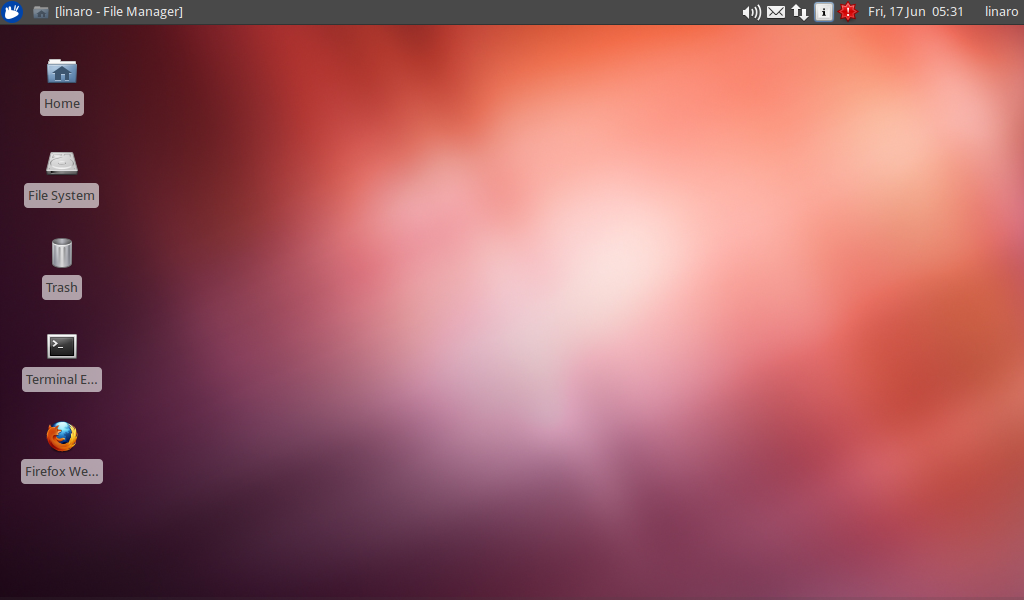
Figure 272: Ubuntu 12 Desktop Screen
SD Test
The IPC supports SD card hot-plug. The figure below shows the message when you plug the SD card into IPC. The IPC will mounts the SD Card to /media/xxxx-xxxx directory.
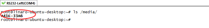
Figure 273: Serial Message
Figure 274: SD Card
USB Flash Disk Test
The USB Flash Disk is like the SD Card. The IPC mounts the USB Flash Disk to /mnt/media_rw/ and /storage/ directory.
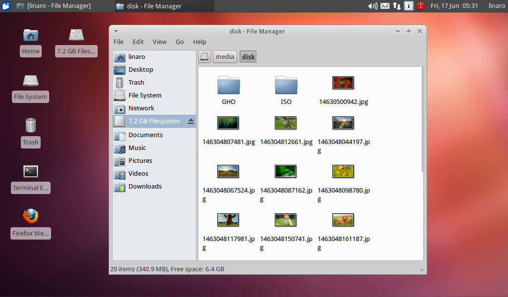
Figure 275: USB flash disk test
SATA Test
The SATA does not support hot-plug, but the Ubuntu 12.04 OS supports NTFS, EXT3, and FAT.
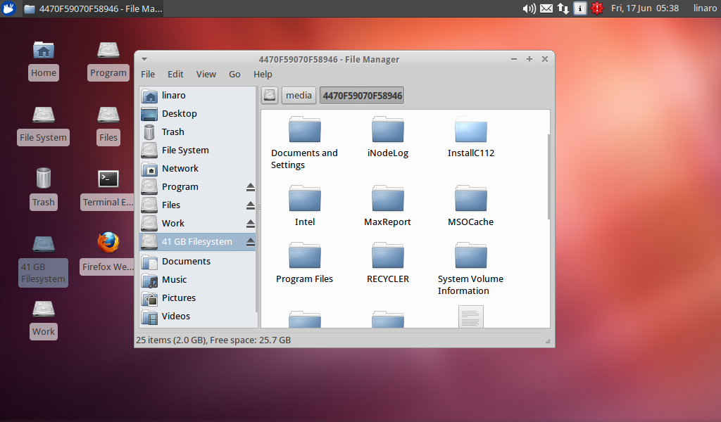
Figure 276: SATA test
Network Test
The network uses DHCP to get IP Addresses. You can get network access if you connect a LAN cable from the IPC to a router.
You can change the IP Address with this command.
# ifconfig eth0 down
# ifconfig eth0 192.168.xx.xxx up
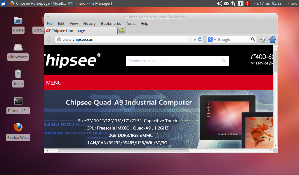
Figure 277: Network Test
Sound Card Test
Please open an audio file in Rhythmbox to test the Sound.
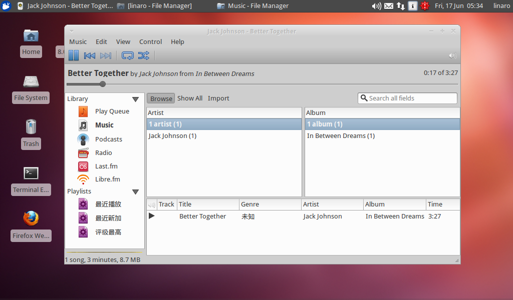
Figure 278: Sound Test
Video Test
Please open a video file to test the Video.

Figure 279: Video Test
HDMI Test
You can reference this document, IMX6Q U-boot Setting HDMI Output For Android.pdf, to learn about performing HDMI tests.
Note
HDMI does not support hot-plug. The sound comes from the HDMI monitor, neither the speaker nor the headset on board.
WIFI Test
You must ensure the IPC has an SDIO Wi-Fi module integrated before performing the Wi-Fi test. If the IPC has an SDIO Wi-Fi Module, you can connect to the Wi-Fi and open a browser to test.
Serial Test
There are five serial ports on the Chipsee IPC: 2 x RS232 and 3 x RS485 (can be customised). Refer to the table below for the available serial device nodes.
Ports |
Device Node |
|---|---|
COM1(RS232, Debug) |
/dev/ttymxc0 |
COM2(RS485) |
/dev/ttymxc1 |
COM3(RS232) |
/dev/ttymxc2 |
COM4(RS485) |
/dev/ttymxc3 |
COM5(RS485) |
/dev/ttymxc4 |
Note
If you use COM2(RS485), you can’t use Bluetooth because COM2(RS485) share pin with Bluetooth.
You can install the SecureCRT or Putty software on a Windows 7 PC to test the serial ports by following these steps:
Connect COM1 on industrial PC board to Windows 7 PC.
Run Serial Port API App to communicate with Windows 7 PC, as shown on the figure below.
CAN Test
Chipsee Industrial PC is equipped with two CAN busses (CAN1 and CAN2). Two devices can be interconnected. You can test the CAN buses by using the HT application but you must add one 120Ω resistor between CAN_H and CAN_L on one of the two Boards, as shown on the figure below.
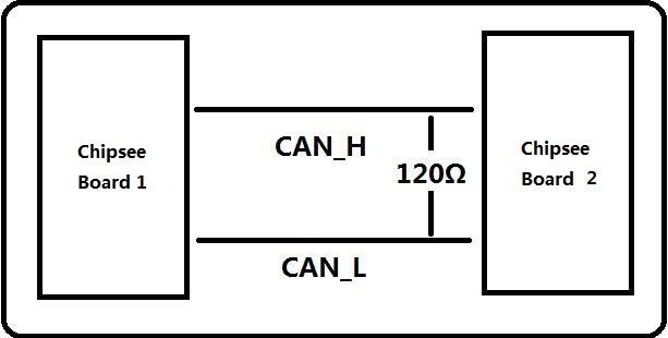
Figure 280: CAN Connect
Note
The Chipsee IPC does not mount the 120Ω matched resistor on all CAN signals by default.
Here are a few examples to test CAN by using CAN units
- Install can-utils
$ sudo apt install can-utils
- Set the bit-rate to 50Kbits/sec with triple sampling using the following command (use ROOT user):
$ sudo ip link set can0 type can bitrate 50000 triple-sampling on
OR
$ sudo canconfig can0 bitrate 50000 ctrlmode triple-sampling on
- Bring up the device using the command:
$ sudo ip link set can0 up
OR
$ sudo canconfig can0 start
- Transfer packets
Transmit 8 bytes with standard packet id number as 0x10
$ sudo cansend can0 -i 0x10 0x11 0x22 0x33 0x44 0x55 0x66 0x77 0x88
Transmit 8 bytes with extended packet id number as 0x800
$ sudo cansend can0 -i 0x800 0x11 0x22 0x33 0x44 0x55 0x66 0x77 0x88 - e
Transmit 20 8 bytes with extended packet id number as 0xFFFFF
$ sudo cansend can0 -i 0xFFFFF 0x11 0x22 0x33 0x44 0x55 0x66 0x77 0x88 -e --loop=20
- Receive data from CAN bus
$ sudo candump can0
- Bring down the device
$ sudo ip link set can0 down
GPIO
There are 8 GPIOs, 4 Output, and 4 Input, they are all isolated. You can control the output or input pin voltage by feeding the VDD_ISO suite voltage. The pin voltage should be from 5V to 24V. Refer to the tables below for a detailed port definition:
Pin Number |
GPIO Number |
|---|---|
11 |
205 |
12 |
106 |
13 |
29 |
14 |
30 |
15 |
28 |
16 |
204 |
17 |
94 |
18 |
95 |
Pin Number |
GPIO Number |
|---|---|
3 |
106 |
4 |
30 |
6 |
95 |
7 |
87 |
8 |
29 |
9 |
28 |
11 |
94 |
12 |
130 |
Note
You need ROOT permissions to control GPIO.
Set gpio106 Output to high or low using this command
# echo  106  > /sys/class/gpio/export                //export gpio106
# echo  out  > /sys/class/gpio/gpio106/direction     //set gpio106 Output
# echo  1  > /sys/class/gpio/gpio106/value           //Set gpio106 high
# echo  0  > /sys/class/gpio/gpio106/value           //Set gpio106 low
Set gpio30 Input using this command
# echo  30  > /sys/class/gpio/export                  //export  gpio30
# echo  in  > /sys/class/gpio/gpio30/direction        //Set  gpio30 input
Un-export gpio30 using this command
# echo 30 > /sys/class/gpio/unexport //un-export gpio30
Ubuntu 12.04 system debug in Windows
In this section, we will discover how to view the Ubuntu 12.04 system via the serial port and debug the system via USB OTG.
Also, we will discover how to install and uninstall applications via USB OTG.
The following operation is under the Windows 7 x64 environment, similar to other Windows platforms.
View Ubuntu 12.04 system via the serial port
Install the SecureCRT or Putty software on a Windows 7 PC to view the Ubuntu 12.04 system via the serial ports.
Follow these steps to view Ubuntu 12.04 system via the serial port:
Connect COM1 on the industrial PC board to Windows 7 PC.
- Open the SecureCRT or Putty software on the Windows 7 PC and configure it as shown on the figure below.
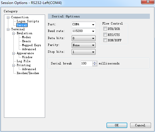
Figure 281: SecureCRT configuration
- Power ON the industrial PC. You will see the serial output information as shown on the figure below.
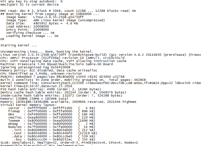
Figure 282: Serial output information
You can communicate with the system when system boot is complete.
QT development
In this chapter, you will learn how to set up the QT development environment, and develop the first QT application on Chipsee IPC boards.
Preparation
Download and install QT4.8.4 and QTCreator2.6.2.
Example — Develop a HelloWorld Program
- Use QtCreator to create a project, named
HelloWorld, as shown on the figure below. 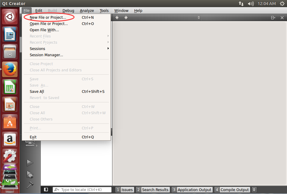
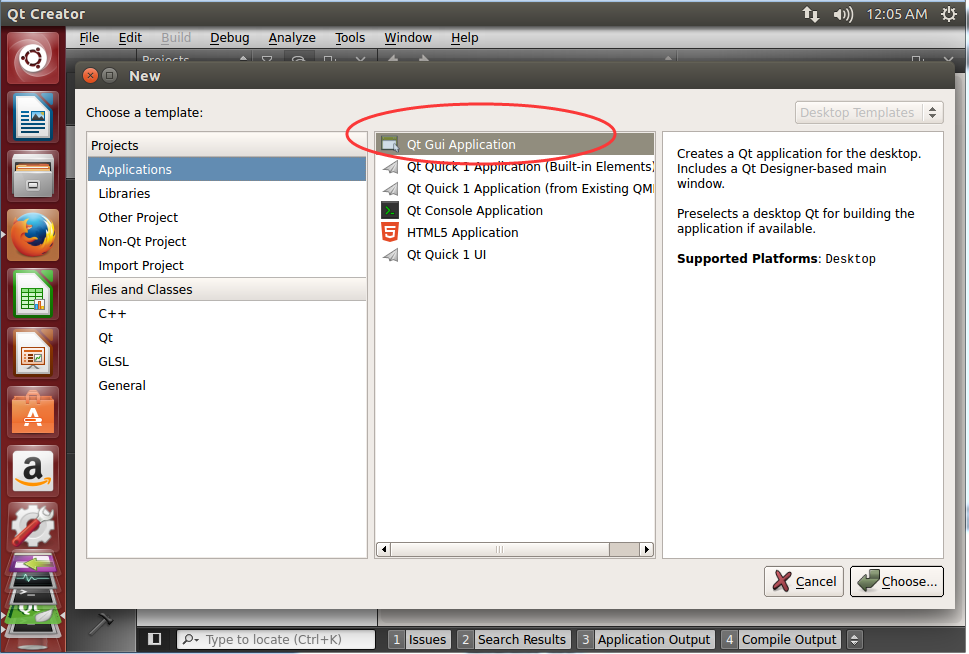
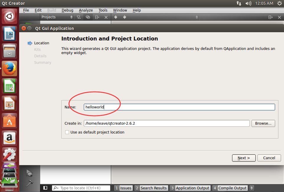
Figure 283: Create Application
- Use QtCreator to create a project, named
- Select IMX kits, as shown on the figure below.
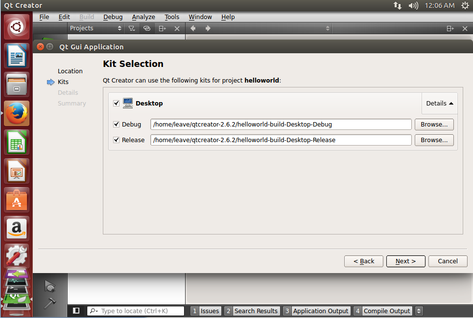
Figure 284: Kit Selection
- Use QMainWindow as the Base class, as shown on the figure below.
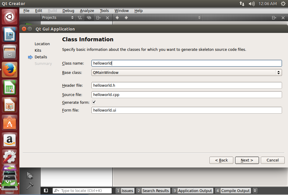
Figure 285: Base Class
- Click the Design icon to add one label widget, as shown on the figure below.
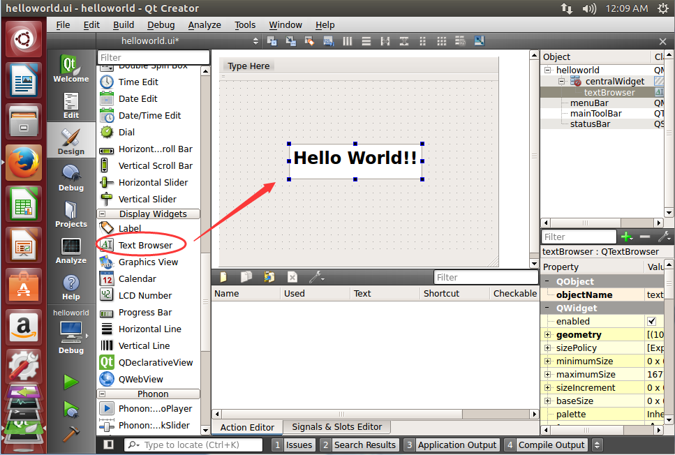
Figure 286: Add Label Widget
- Click on the Build icon to build app, as shown on the figure below.
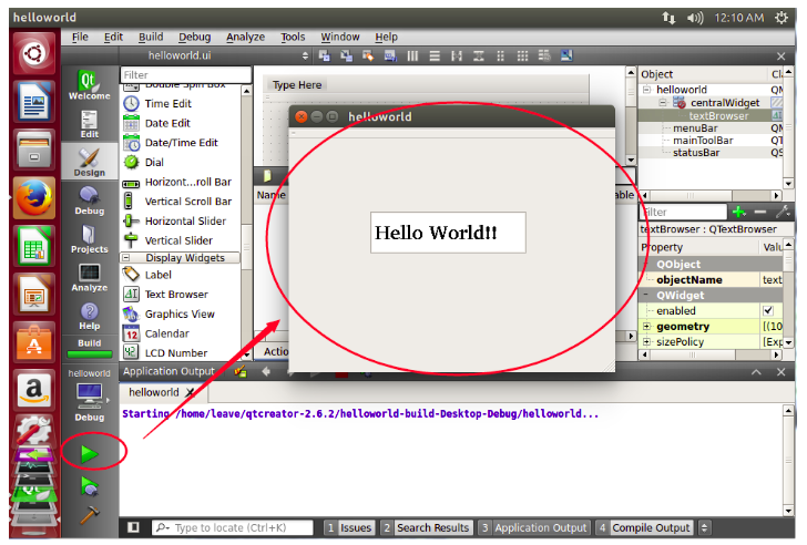
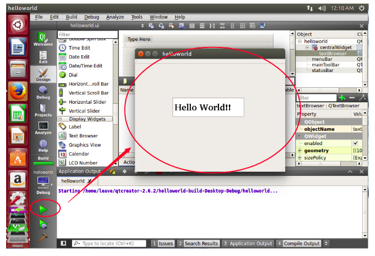
Figure 287: Build App
- Copy the
Helloworldapp from the /home/leave/qt-creator2.6.2/helloworld to the IPC board’s /home/root/ directory and use the following command to run it: # export DISPLAY=:0.0 # ./HelloWorld
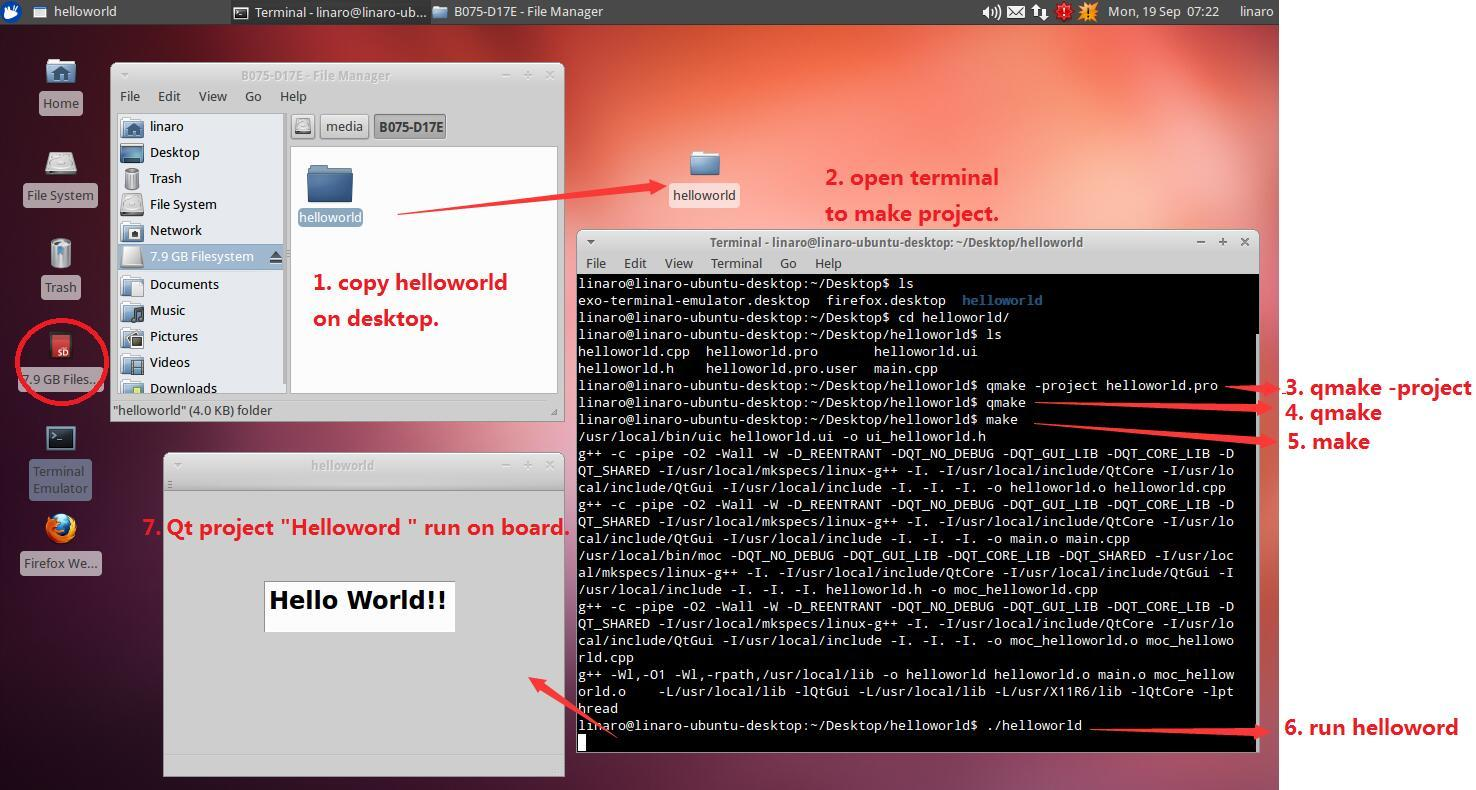
Figure 288: Install app on IPC
Note
The command qmake -project, qmake, & make must be done on board, like above.
- Copy the
- Add a startup icon for
helloworld. $ cd /usr/share/applications $ sudo vi helloworld.desktop
- Add a startup icon for
- Add the following content in the
helloworld.desktopfile, as shown on the figure below. [Desktop Entry] Version=1.0 Encoding=UTF-8 Type=Application Name=helloworld Comment=helloworld NoDisplay=true Exec=/home/linaro/Desktop/helloworld/helloworld %f // the path of qt binary. Icon=/home/linaro/Desktop/helloworld/helloworld.png // you can replace it by you own icon. Name[en_US]=helloworld
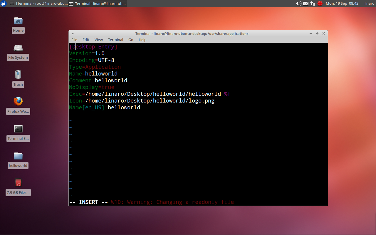
Figure 289: Add app to desktop
- Add the following content in the
- Locate the directory with app icon and copy it to the desktop, as shown on the figure below:
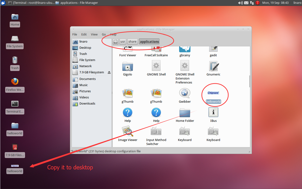
Figure 290: Copy app icon
Disclaimer
This document is provided strictly for informational purposes. Its contents are subject to change without notice. Chipsee assumes no responsibility for any errors that may occur in this document. Furthermore, Chipsee reserves the right to alter the hardware, software, and/or specifications set forth herein at any time without prior notice and undertakes no obligation to update the information contained in this document.
While every effort has been made to ensure the accuracy of the information contained herein, this document is not guaranteed to be error-free. Further, it does not offer any warranties or conditions, whether expressed orally or implied in law, including implied warranties and conditions of merchantability or fitness for a particular purpose. We specifically disclaim any liability with respect to this document, and no contractual obligations are formed either directly or indirectly by this document.
Despite our best efforts to maintain the accuracy of the information in this document, we assume no responsibility for errors or omissions, nor for damages resulting from the use of the information herein. Please note that Chipsee products are not authorized for use as critical components in life support devices or systems.
Technical Support
If you encounter any difficulties or have questions related to this document, we encourage you to refer to our other documentation for potential solutions. If you cannot find the solution you’re looking for, feel free to contact us. Please email Chipsee Technical Support at support@chipsee.com, providing all relevant information. We value your queries and suggestions and are committed to providing you with the assistance you require.